Engine Stage 3
 21 February 2007, 09:09 PM
#1

Note: If you have problems changing pages on this article, please ensure you have the following option set in your USERCP -> "Number of Posts to Show Per Page" set to "Use Forum Default"
Whilst it has been a very long (but productive) journey starting way back in mid 2005, the Spec C has changed considerably, but we are not going to end there.
SUPPORT AND SUPPLY OF PRODUCTS AND SERVICES FOR ENGINE - STAGE 3

Powerstation - Rolling Road Facility, Mapping, Technical Help/Guidance, Product Supplier, Workshop Facilities (fitment/testing of products)

AET Turbos - Product Supplier, Rolling Road Facility, Technical Help/Guidance

ScoobySport - Technical Help

Litchfield Imports - Product Supplier, Technical Help

API - Technical Help/Guidance, Product Supplier, Workshop Facilities (fitment/testing of products)

Tracktive Solutions - Product Supplier, Mapping, Technical Help/Guidance, Workshop Facilities(fitment/testing of products)

Lateral Performance - Product Supplier, Technical Help/Guidance
Of course it is not all about choosing mods, banging them on and then declaring the world. A lot of time has been spent carefully data logging specifics (over a long period of time) to ensure that all is well, and that the car can really be tagged as a very reliable all rounder.
Stage 2 engine mods saw the car perform in several competition events in 2006 (ScoobyLive, Time Attack, TOTB, Tuner GP and various performance / handling testing). Some may be amazed to hear that we never encountered one single mechanical problem and the only item the car required was routine servicing between events. To me, this is a real world test of a vehicles state of tune and is invaluable feedback for people potentially looking to modify their car. To even contemplate in winning, you have to at first finish!
Many myths around what is required during modifications of the Newage power plant have been dispelled, and whilst various other authorities will argue till they are blue in the face that x and y works and is required, I think the work and results that have been completed up to now speaks for itself.
Whilst it has been a very long (but productive) journey starting way back in mid 2005, the Spec C has changed considerably, but we are not going to end there.
SUPPORT AND SUPPLY OF PRODUCTS AND SERVICES FOR ENGINE - STAGE 3
Powerstation - Rolling Road Facility, Mapping, Technical Help/Guidance, Product Supplier, Workshop Facilities (fitment/testing of products)
AET Turbos - Product Supplier, Rolling Road Facility, Technical Help/Guidance
ScoobySport - Technical Help
Litchfield Imports - Product Supplier, Technical Help
API - Technical Help/Guidance, Product Supplier, Workshop Facilities (fitment/testing of products)
Tracktive Solutions - Product Supplier, Mapping, Technical Help/Guidance, Workshop Facilities(fitment/testing of products)
Lateral Performance - Product Supplier, Technical Help/Guidance
Of course it is not all about choosing mods, banging them on and then declaring the world. A lot of time has been spent carefully data logging specifics (over a long period of time) to ensure that all is well, and that the car can really be tagged as a very reliable all rounder.
Stage 2 engine mods saw the car perform in several competition events in 2006 (ScoobyLive, Time Attack, TOTB, Tuner GP and various performance / handling testing). Some may be amazed to hear that we never encountered one single mechanical problem and the only item the car required was routine servicing between events. To me, this is a real world test of a vehicles state of tune and is invaluable feedback for people potentially looking to modify their car. To even contemplate in winning, you have to at first finish!
Many myths around what is required during modifications of the Newage power plant have been dispelled, and whilst various other authorities will argue till they are blue in the face that x and y works and is required, I think the work and results that have been completed up to now speaks for itself.
Last edited by ex-webby; 19 February 2008 at 05:15 PM.
 15 January 2008, 07:24 PM
#2
Too many people still to this day only look at peak figures….. believe me, this means nothing in the real world and the quicker people realise this the better. Personally I would rather have a better power band and the utmost reliability for the sake of a couple of BHP less.
People also carry on about Rolling Road tuning compared to Road Mapping. As an end user I don’t care about the intricacies of the benefits of one over the other. The Spec C has always been mapped on a rolling road (with tweaks made based on road driving feedback), but ultimately the car delivered and stayed in one piece….. this is what is important to me as a customer, so is all I need to know. What ever it takes to get the job done me thinks!
Initially we made the concious decision to look at what could be done, that was effective (i.e. actually works) and within a reasonable budget. What was achieved during Stage 1 and 2 met those requirements quite nicely.
Car modifications you can always take that one step too far and ruin an already brilliant car. With this in mind the original thoughts were along the lines of "Stage 2 - Thats it!".... unfortunately we were kidding ourselves to think that further development would not take place!
We were already thinking about what could be done with Stage 3 prior to finishng Stage 2, and we alluded to what some of these options could be.
Those areas of interest were:
1) Big BHP – Totally new engine (either 2.33 or 2.5ltr) normal position turbo
2) Big BHP – Totally new engine (either 2.33 or 2.5ltr) rotated position turbo
3) Keep with the staged approach, trying other various modifications in specific areas
Where do we start!!!!
Let's make this simple.......
a) 2.5ltr was the weapon of choice since PowerStation / Litchfield Imports had already ploughed endless hours of development with Cosworth in to a reliable and powerful engine. This made the interest value of the 2.5 more, especially since the UK market would only be getting 2.5 engines in current and future STi's.
Last edited by ex-webby; 05 February 2008 at 10:08 PM.
15 January 2008, 07:25 PM
#3
b) We already knew that big BHP together with a spec'd engine is normally achieved by having a rotated "clocked" turbo arrangement. Whilst this was the proven way, we really wanted to see how far the standard position turbo "straight drop in arrangement" could be pushed, as 500bhp with this arrangement was deemed to be luck more than a given. In the true nature of previous articles we wanted to see if this was really the case and whether with better choice of parts we could achieve what was not the norm.
c) Lets be honest.... small tweaks of the current platform were now out of the question. We wanted a much faster and much more powerful car!
See... that was not that hard was it (we wish)!!
So to be clear on our remit we decided on the following:
2.5L Engine configuration
Standard position turbo
500+bhp (I know we have harped on about peak figure chasing, but we needed some form of goal)
One hefty development budget (we needed to be fairly realistic on this one)
Above all the car must remain as driveable as it was after Stage 2
A tall order.... we will wait and see!
STAGE 3 - ENGINE MODIFICATIONS
We never envisaged we would be thinking about a Stage 3 for the engine, let alone actually going through with it.... best laid plans and all that. Above all it has showed how addictive this tuning is.... like pringles, once you start you can't stop.
We had achieved very good levels of performance by the end of Stage 1 and 2, with driveability being goal. As mentioned earlier this was one key area we wanted to carry through Stage 3.
Since we would be working from a blank "no holds barred" point of view, we wanted to include a number of discussions with different professionals about how we could achieve our goal. This ultimately meant we would be working with a number of companies that had not been involved in this project before.
Previous supporters namely PowerStation, Litchfield Imports, API and ScoobySport were already onboard and eager to carry on support, together with new insight and help from AET Turbos, Lateral Performance and last but by no means least Tracktive Solutions.
As with previous articles we have decided to give some background information on these new supporters of the Project during specific areas of this publication.
Last edited by ex-webby; 05 February 2008 at 10:10 PM.
15 January 2008, 08:51 PM
#4
So.... without further ado let the quest for huge horses commence!!!
The Engine
The core part of this modification level was always going to be about the engine. Since we had decided to go the 2.5l route, the obvious choice based on experience already gained had to be the mighty Cosworth 2.5l powerplant.
Let's be honest, anyone who has not heard of Cosworth probably is not human....their track record and achievements are legendary.
Not to be taken in by any previous accomplishments of a single manufacturer, however successful it has been, we needed to be assured of current standings in the world of everything Subaru. PowerStation and Litchfield Imports had already undergone several months and a complete race season of development / production with Cosworth of their 2.5l engine that took pride place within the engine bay of PowerStations / Litchfields 2006 Time Attack winning Spec C. Not only were Litchfield over the moon with their well derserved Time Attack win, but what many people did not know, this development not only took place to win Time Attack, but it was also paramount to the production of the latest Subaru Type25 road car.
Supported with knowledge from PowerStation the writing was perhaps on the wall regards to what the latest incarnation of the Type25 would turn in to.... probably the best road going Subaru of all time. Since our thoughts of future modifications to our very own Spec C had been initiated part way through 2006, we chose to follow the progress of PowerStation / Litchfield's race car (and development of the Type25 road car) very closely. Fortunately because of the trusting relationship we had forged with these two companies, we were also given insight in to some of the secrets of engineering around this race car along with indepth "teachings" on issues they had discovered and how they rectified them. All of this was invaluable to us making our final decision on preferred engine platform.
Let's get down to the nitty gritty, of what is a work of art.
The specification is very comprehensive and just to underline the fact, this engine is the same specification that was part of the 600+bhp Type25 Race Car and virtually the same specification as the 415bhp Type25 Road Car. Anyone that knows of Litchfields previous Type25 road car will appreciate that driveability and "standard" car feel were paramount. To suggest an engine capable of these power levels (this is quite a broad range) whilst remaining "standard" to the ear and senses was unheard of during early Subaru tuning circles. How things have advanced is truly outstanding.
Last edited by ex-webby; 05 February 2008 at 10:12 PM.
15 January 2008, 09:11 PM
#5
So whats in this box of tricks that makes it a solid multi-purpose platform to use......
Cosworth short block (bottom end)
 Cosworth EJ25 (STI) short block has gone through countless hours of dyno evaluation to determine the best combination of parts to guarantee maximum reliable performance. Each EJ25 short block starts with a brand new Subaru case. The case is inspected and then the bores are honed to perfection to receive Cosworth Forged Pistons. The rotating assembly is then balanced, this includes a new STI Forged crank and Cosworth Forged H-Beam Connecting Rods to within .5 gram. The select parts are professionally assembled by one of Cosworth�s skilled engine builders using their own coated, tri metal race spec bearings.
 Cosworth CNC ported cylinder heads feature dyno tested and flow bench proven ports, engineered for maximum real world power. Each new cylinder head is ported on a 5 axis machine to ensure consistency and perfect port shape every time. Additionally, larger intake (+1mm) and exhaust valves (+1mm) are utilized to help increase flow. Cosworth CNC ported Big Valve cylinder heads come complete with a performance valve job, hi rev (max 10,500rpm) valve springs with titanium retainers and are ready to install. Perfect for big turbo applications.
Cosworth short block (bottom end)
- New Subaru EJ25 STI Engine Case
- New Subaru STI Forged Crankshaft
- Cosworth Forged Connecting Rods
- Cosworth Forged Pistons
- Cosworth High Performance Piston Rings
- Cosworth Race Spec coated Tri- Metal Bearings
- Balanced and Professionally assembled
- CNC Ported/machine finished ports - New OE Castings
- Hand blended finish work
- Intake 22% Increased Flow (max)
- Exhaust 41% Increased Flow (max)
- 4-angle Inlet Valve job
- 3-angle & radiused Exhaust Valve job
- Valves are lapped
- Back-Cut Inlet Valves
- Heads are Ultra Sonic cleaned prior to assembly
- Heads are Serialized and sport a machined Cosworth logo
- +1mm Stainless Steel Intake Valves (1800 degrees max.)
- +1mm Inconel Exhaust Valves (2400 degrees max.)
- Performance Valve Springs
- Titanium Retainers
- Hardened Steel Spring Platforms
- Knife Edge port divider
Last edited by ex-webby; 15 January 2008 at 09:29 PM.
15 January 2008, 09:47 PM
#6
As you may imagine this type of engine specification does not come cheap, but remember neither does reliability. This engine base specification had undergone a strenuous development / testing cycle and whilst most 2.5l engines are rarely able to rev (and still make power), this specification easily revs past 8k rpm. Having a 2.5l power plant that makes big torque/power figures, yet has the rev range of a 2l engine is something not to be dismissed. Couple this with the fact that not only are you having an engine built by one of the best names in engineering, but you are also purchasing a complete engine and not a machined secondhand one. Price details will be explained further on within this article.
 This might all sound irrelevant, but even the delivery of a Cosworth Engine is something quite special. Each engine being assembled by Cosworth themselves is delivered on a crate in a Cosworth Box, with "Power by Cosworth" emblazoned on each side. Not mind blowing, but it adds to the overall "experience". It certainly got us excited!
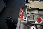 Each engine also comes with a build specification sheet from Cosworth, along with a unique Cosworth Engine plaque (you can find out the real Cosworth engines now!), which is situated towards the back of the block on the right hand side as you look at the engine in situ. The engine for our car was serial number: SB0059.
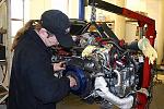
 So, with the engine in the workshop it was time to prep the new engine for insertion in to the Spec C. This takes a number of hours of preparation as specific anxillaries had to be taken off the existing Spec C engine, and of course the removal in the first instance. Bye Bye old trusty 2l!
To be frank, to someone not appreciating this process, to see someone as experienced as Nick at PowerStation removing an engine in such a quick and knowledgable manner is quite awe inspiring. To the customer, under the bonnet is a plethora of pipes and shiny bits and whilst we may think that we know what is what, to be able to remove an engine (what could quite possibly be done blind folded by a professional) with such ease is quite astounding.
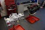 Anyway, both engines were now side by side on their own engine stands. To the uneducated they both looked like the same piece of metal (albeit the standard engine still had all the attached anxillaries).... how much further from the truth could that possibly be! Basic logic states that we seem to take for granted that an engine that has a 25% increase in capacity is still the same physical size. It is not until you realise what makes that capacity increase possible, do you appreciate the logistics. Machining the existing block to take wider liners and wider pistons enables this to happen.
To be frank, to someone not appreciating this process, to see someone as experienced as Nick at PowerStation removing an engine in such a quick and knowledgable manner is quite awe inspiring. To the customer, under the bonnet is a plethora of pipes and shiny bits and whilst we may think that we know what is what, to be able to remove an engine (what could quite possibly be done blind folded by a professional) with such ease is quite astounding.
Last edited by ex-webby; 05 February 2008 at 10:14 PM.
16 January 2008, 06:27 PM
#7
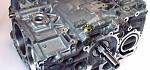
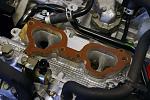
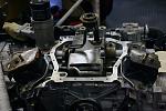
With the Cosworth engine now on an engine stand is was an oppourtune time to look at the shiny bits. Unfortunately due to the fact that the engine was complete (heads and block) the real bits (on the inside) could not be viewed. Fortunately we could still look at, and compare, bits that were viewable like the inlet ports. This is where the air comes in to the engine after the air filter, turbo and intercooler. If you have an STi it is fed in to these ports from your red inlet manifold, which is easily recognisable from under the bonnet.
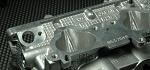
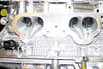 As you can see in the upper most image to the right (apart from looking very shiny) the inlet has a sharp divider in the middle. Either side of the divider is the port to each inlet valve (which you can see quite clearly). This divider is part of the Cosworth Head Specification, known as a Knife Edge Devider. If you look at the next image down to the right (which is the same port, but on the standard 2l engine), you will notice this devider does not exist. The divider is there to promote faster flow with less turbulence. Faster should mean denser and cumulates in to a bigger, responsive bang. You will also see comparing the two images
 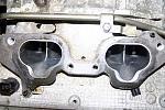 that the Cosworth ports are actually bigger. This is especially noticeable around the valve stem base. In this case, more space is greater airflow, which will increase power capabilities as regards to it's creation and sustainability. As with anything to do with porting, you must get it right.... too much and whilst you may achieve a specific power output, you could do this at the sacrifice of response / torque. A lot of time has been spent flow testing these heads to ensure they meet requirements and do not sacrifice response / torque in the process.
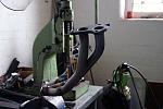
Turbo Inlet Pipe
As part of the process of building the Cosworth engine back up so it could be put back in the gapping hole left in the Spec C, another area of modification was concerning the inlet pipe. As in Stage 1, we had already looked at changing the standard inlet pipe from the air filter to the turbo, but this time since we knew we were going to use a much bigger turbo inlet, we needed to look at changing the size of the inlet pipe that connects to this turbo inlet.
Litchfield Imports had already completed some development of a new inlet pipe for the Type25 Road Car, to aid fitment and air feed to it's larger inlet turbo specification. Since we were going to retain the standard fit turbo and knew we would be utilising a similar inlet size we chose to take advantage of this newer developed inlet pipe supplied by SFS.
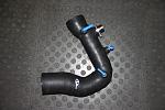 Unfortunately we never had another standard pipe (the original engine anxillaries were still connected to the 2l Spec C engine at this stage) to show you the comparison, but as you may be able to tell from the image on the right..... this thing is H U G E!
Turbo Inlet Pipe
As part of the process of building the Cosworth engine back up so it could be put back in the gapping hole left in the Spec C, another area of modification was concerning the inlet pipe. As in Stage 1, we had already looked at changing the standard inlet pipe from the air filter to the turbo, but this time since we knew we were going to use a much bigger turbo inlet, we needed to look at changing the size of the inlet pipe that connects to this turbo inlet.
Litchfield Imports had already completed some development of a new inlet pipe for the Type25 Road Car, to aid fitment and air feed to it's larger inlet turbo specification. Since we were going to retain the standard fit turbo and knew we would be utilising a similar inlet size we chose to take advantage of this newer developed inlet pipe supplied by SFS.
Last edited by ex-webby; 12 February 2008 at 10:40 AM.
Trending Topics
16 January 2008, 08:33 PM
#8
The inlet pipe is not only bigger, but it is also one piece as regards to the original pipe work set-up, which has another pipe between the end of the standard inlet pipe between itself and the MAF. This would also aid with air flow, being one piece.
Inlet Manifold Spacers
Having an inlet pipe and proposed bigger turbo, we would of ran in to a problem had we not used inlet manifold spacers. Inlet manifold spacers are probably something you have heard of, without actually realising what they are or do!
Anyone that has removed or tried to fit a turbo inlet pipe (perhaps a larger one) will realise that there is not much space between the inlet manifold and the block.... especially whilst trying to negotiate an inlet pipe perhaps on to a larger inlet (compressor cover) on a turbo. One way you can circumvent this is by raising the inlet manifold to widen the space between that and the block. Whilst this is one benefit of inlet manifold spacers, it is certainly not the only and in most cases is not the main reason for using these spacers.
 Another benefit of these spacers is to decrease the terminal conductiveness between the inlet manifold (from heat rise of the block and general engine area), this in turn pre-heating the air contained within the inlet manifold prior to it entering the inlet of the engine. Heat transfer from the block to the inlet manifold is the primary concern here and by using a spacer (made of something that does not conduct heat as well as metal to metal does) this can be greatly reduced.
A bonus for us as it kills two birds with one stone!
Turbo
With the inlet manifold spacers sorted, we would at least now be in a position to sort the fitment of a turbo (now that we have a bit more space).
First off... what does "Rotated" and "Standard Position" mean?
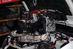
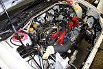
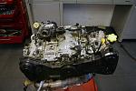 Well, as it implies, standard position is exactly that. A turbo that is mounted in it's standard position with the inlet of the turbo viewable between the inlet manifold and block, which requires an inlet pipe (as already shown) with a 90deg (or there abouts) bend at the end to enable routing to the airbox or induction kit. Seeing the turbo easily would mean that it is pointing straight at you (inlet towards you) if you opened the bonnet and looked at the engine head on. This can be clearly seen in the image to the left, which shows the 2l Spec C engine (minus the inlet manifold and other anxillaries) with the "Standard Position" turbo still attached.
Inlet Manifold Spacers
Having an inlet pipe and proposed bigger turbo, we would of ran in to a problem had we not used inlet manifold spacers. Inlet manifold spacers are probably something you have heard of, without actually realising what they are or do!
Anyone that has removed or tried to fit a turbo inlet pipe (perhaps a larger one) will realise that there is not much space between the inlet manifold and the block.... especially whilst trying to negotiate an inlet pipe perhaps on to a larger inlet (compressor cover) on a turbo. One way you can circumvent this is by raising the inlet manifold to widen the space between that and the block. Whilst this is one benefit of inlet manifold spacers, it is certainly not the only and in most cases is not the main reason for using these spacers.
A bonus for us as it kills two birds with one stone!
Turbo
With the inlet manifold spacers sorted, we would at least now be in a position to sort the fitment of a turbo (now that we have a bit more space).
First off... what does "Rotated" and "Standard Position" mean?
Last edited by ex-webby; 05 February 2008 at 10:43 PM.
16 January 2008, 09:06 PM
#9
Due to the nature of the standard position, you are indeed limited for space (even with the benefit of inlet manifold spacers) which inherently means you are limited to turbo (both compressor side and exhaust side), which ultimately means you are limited to power. More on this further on.
A "Rotated" mount turbo again is just that. Imagine the picture above, but with the turbo (at least) moved by several degrees to clockwise (hence the term "clocked" as well) so the inlet is now pointing towards the bottom left area of the image's left hand head. You would also find the turbo perhaps to be tilted slightly downwards at the back, so it comes up from the back of the engine, more than being level across the top. The advantages of a rotated mount turbo is bigger turbos can be utilised, resulting in more power, together with the easier use of external wastegates to control boost better.
So why not use a rotated mount turbo if this is supposed to be a ***** out project?
Fair point but:
a) we didn't look at this as being ***** out - that to us would mean 650+bhp and was not something we were aiming for in reality
b) we wanted to see what could be done with what was known as being a limiting (i.e. hard to get 500bhp) factor
c) standard fit turbos are more easily relatable to most of the community for their own conversions
Further to this discision we also wanted to move away from the previous twin scroll turbo set-up (explained in Engine Stage 2). Whilst the twin scroll set-up was prime to the previous engines response, we knew the added torque and spool up characteristics the Cosworth engine provided would enable us to utilise a far simplier single scroll configuration. Couple this with the fact that development for this power level of twin scroll was virtually non-existant (due to costs involved in casting larger exhaust housings), it was virtually a no brainer at this stage.
With all this in mind we had already started to discuss our requirements with one of the biggest turbo manufacturers in the UK... AET Turbos.
AET Turbos - Explained
AET Turbos (AET) began in 1974, satisfying the need for turbocharger reconditioning in the commercial diesel market. Tony Taylor, founder and present chairman of AET, started the business after working for Holset Turbochargers from 1966, initially as their first ever Senior Sales Engineer and later as Manager For Special Projects. Tony has built the business along with his son, Andy, who joined the company in 1992 after completing his honours degree in Computer Aided Engineering and who has been Managing Director since 2002.
Last edited by ex-webby; 05 February 2008 at 10:45 PM.
16 January 2008, 09:10 PM
#10
AET has had many collaborations with the likes of:
- Tom Hammond�s 700HP Audi Quattro Pikes peak car
- Mercedes� Works Truck Racing Team with Barry Sheen
- Mitsubishi UK � Turbo development for the Mitsubishi Colt
- Tony Sugden�s Cossy powered 550HP Skoda GT car � Tony is possibly the most successful club racer alive today
- Numerous Porsche Grp C teams from the 1980�s
- John Fitzpatrick�s Skoll Bandit Grp C Porsche 956 team from the US
- GTI Engineering�s Porsche 956 Le Mans
- Richard Clear Racing with Tiff Nidell
- The world beating blue Coral Porsche GT1 from G-Force
- Cirtek Racing Porsche GT2 winning cars
- Janspeed
- Brian Henton driving the Hart 1.5Ltr turbo F1 car
- Hannu Mikkola and Michelle Mouton running Audi UK/David Sutton/Terry Hoyle prepared Audi Quattro�s
Last edited by ex-webby; 04 February 2008 at 09:03 PM.
16 January 2008, 09:10 PM
#11
Over time, AET have expanded their motorsport product range to compliment their record breaking turbochargers. This range includes being appointed sole UK importer and distributor for Turbosmart�s award winning range of boosting products which are regarded as the best in the world, and can be found on nearly every Championship winning vehicle. Their range is constantly expanding and includes BOV�s, boost control systems, external wastegates, fuel regulators, FCD�s and silicone hoses.
AET is also the UK importer and distributor of Hyperflow Intercooling Systems from Australia. Hyperflow designs and builds some of the most innovative and efficient intercooler kits for Subaru and Mitsubishi. Other products for the Subaru market include billet racing sumps, cold air intake systems, catch cans and oil coolers.
Last edited by ex-webby; 04 February 2008 at 09:06 PM.
16 January 2008, 09:33 PM
#12
Turbo - continued
With the wealth of experience AET Turbos have you can understand why we chose them as the supplier of choice for this stage of modification!
Ok... so we were sticking with a standard mount turbo, but we needed something that would hopefully meet our target of 500bhp. This was perhaps being slightly naive, especially when we wanted to do this on normal pump fuel (VPower) and without the need to run rocket ship boost. But based on all the development that PowerStation, Litchfield Imports & Cosworth had done on the engine platform we hoped we would be on the right track.
 With our requirements to hand AET at first subscribed one of their Subaru "drop in" turbos to test. AET (and us) realised that this would not be the first turbo (as further development would need to be done), but at least it would provide a benchmark and allow us to judge how the turbo and engine (plus other new anxillaries discussed further on) all
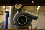
 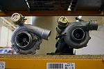 worked together. This first turbo was chosen from AET's VIPER range of performance turbos, and was based on a Garrett GT core using a standard fit exhaust housing and hybrid compressor housing utilising the latest specification of ball bearing core and blade set-up.
The first image above right shows the AET Viper turbo in all it's glory. Hard to see the size difference in this image, you can look at the second image below which shows the AET turbo against the original Spec C turbo. Whilst the turbo is clearly bigger, the naive ones (i.e. ME) never thought the physical size could dictate a turbo of delivering the power required. I was immediately put right by AET as it is not always the outside you should be looking at, but the inside....... that is where the magic begins. Who was I to argue!
With the turbo in our hands it was time to carry on with the engine build.
Up-Pipe
 One issue that was slightly glossed over by myself with PowerStation, was that whilst the turbo would be a direct fit replacement we wanted to keep the original twin scroll headers. Not only would this hopefully help response / spool but as these headers were tubular they had very good flow. This unfortunately meant PowerStation had to fabricate a twin in to single up-pipe (as the new turbo was a single scroll unit). Luckily Litchfield Imports had a twin to single scroll up-pipe (but with a Garrett turbo end) available which was for use with their Type25 Road Car. Nick at PowerStation soon took to the task of taking ends from one pipe to another to make a custom up-pipe for this specific configuration.
With the wealth of experience AET Turbos have you can understand why we chose them as the supplier of choice for this stage of modification!
Ok... so we were sticking with a standard mount turbo, but we needed something that would hopefully meet our target of 500bhp. This was perhaps being slightly naive, especially when we wanted to do this on normal pump fuel (VPower) and without the need to run rocket ship boost. But based on all the development that PowerStation, Litchfield Imports & Cosworth had done on the engine platform we hoped we would be on the right track.
The first image above right shows the AET Viper turbo in all it's glory. Hard to see the size difference in this image, you can look at the second image below which shows the AET turbo against the original Spec C turbo. Whilst the turbo is clearly bigger, the naive ones (i.e. ME) never thought the physical size could dictate a turbo of delivering the power required. I was immediately put right by AET as it is not always the outside you should be looking at, but the inside....... that is where the magic begins. Who was I to argue!
With the turbo in our hands it was time to carry on with the engine build.
Up-Pipe
Last edited by ex-webby; 05 February 2008 at 10:47 PM.
16 January 2008, 10:06 PM
#13
With many of the previous 2l anxillaries already transferred on to the Cosworth engine, things were really starting to take shape. The engine was starting to look like an engine again and great progress was being made on the "extras" that were being fitted along the way.
Clutch
With this is mind we thought of no one better to discuss our requirements with than the resident ScoobyNet clutch experts... API Engines.
As you can see from the pictures to the right, this is one mean looking bit of kit.
One of our concerns would be the clutch feel, as we had the understanding that these types of clutch felt no where near as good (or easy to use) as a standard ceramic type. API assured us that whilst the bite would be harder the actual pedal feel would be the same. Again, this was one area we would not know until we had actually driven the car... so here's to hoping.
Last edited by ex-webby; 05 February 2008 at 10:48 PM.
17 January 2008, 06:22 PM
#14
This Cusco unit is intended for both fast road and track use with excellent feel and useability. The diaphram is designed for smooth and light use. The carbon rich facing used on the disc has a ventilated centre plate. Combined with a self leveling system, which balances equal wear on both the flywheel and transmission side of the disc to promote longer clutch life.
Mated with one of API's lightened flywheels (to enable the car to rev quicker and cleaner) we were hopeful that this excellent combination of Cusco Twin Plate Clutch and API Flywheel would not only be reliable, but also handle the type of power and use we hoped it would.
Injectors
Next item that needed to be upraated then!!
Stage 1 and Stage 2 had been content with it's fuel supply via the standard 500cc STi "Pinks" injectors. These "Pinks" are the highest rated, standard fit injectors and were just about at their limit at 380bhp in the previous stage of conversion. With major changes ahead we knew that we would need to fit bigger injectors that could supply enough go go juice for the perceived power level.
What better company to discuss this than Lateral Performance.
Lateral Performance - Explained
Mark Aigin owner of Lateral Performance, started off with his interest in Subaru's way back in 1998 with his own STi v4. As some of you may remember, those were the days which saw very few Subaru Specialists, with no one offering much more beyond your mandatory exhuast back box and the odd bolt on part.
Mark became interested in gaining more power from his car and started to experiment with various ideas. Mark eventually moved on to testing the Link ECU, together with bigger turbo's which saw his car move towards the 400bhp mark! You may not think this is outstanding nowadays, but when Mark was reaching this heady target, it was certainly not the norm .
Mark's presence on ScoobyNet and smaller Subaru forums prompted a number of community members asking Mark for advice, based on this valuable and knowledgeable experience learnt. After an increasing number of members experiencing similar successes based on Mark's guidance, it got to the point where Mark decided his experience and knowledge should be turned into a formal business, and in 2002 Lateral Peformance was formed!
Last edited by ex-webby; 12 February 2008 at 10:53 AM.
17 January 2008, 08:26 PM
#15
Lateral's catalogue of knowledge, products and services has grown to a "one stop" shop for engines, and engine related parts. With a wide range of high quality services / products available, Lateral prides itself in supplying parts , and services that are of the highest quality tried and tested . Some of these products and services include:
Injectors - continued
Since PowerStations preferred route was to keep with the standard fuel pressure, we needed injectors out of the box that would cope with around 500bhp as the target. A number of tuners decide to raise fuel pressure, hence giving more scope to injector capacity, but this is something that PowerStation were against as they deem it as unnecessary if the correct sized injector is spec'd for the job at hand (especially since the standard fuel pressure regulator that Subaru fitted is more than up to the job of supplying a good fuel pressure rate). Of course this can become problematic if you decide you want to go beyond the initial capabilities, but we did not see this as a problem we would encounter.
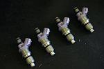 With the above requirements Lateral Performance suggested the use of 800cc (these would be top feed as opposed to side feed that is used for earlier type Imprezas) injectors, as these would be about right for the required supply of a 500bhp set-up. Something else that Lateral suggested was that these injectors were flow matched. What this means is that each injector is flow tested (put on a test rig with pressurised fluid - this fluid quantity over a given period of time is then measured to equate to a flow rate) to ensure a complete set (in this case four) were all flowing at the same rates. You may be surprised to hear that just because each injector from a single manufacturer is supposed to be the same (as in flow rate) this is not always the case. Obviously it makes sense that for all manner of reasons that each injector is matched but not every supplier will ensure this..... it is a worthy note and something perhaps you may want to clarify when buying injectors. Since this is something that Lateral do as a matter of cause, you can be rest assured that what they supply is up to the job.
One other issue with increased injector size (especially around this size) is the fact it can be very hard for the ECU to control the fueling on part throttle and idle etc. This is mainly due to the amount of fuel that is flowed (remember the injectors are bigger as in they flow more fuel under any given pressure than an equivalent smaller flow rated injector) and that when the engine is either idling or on part throttle all the calibration is wrong. This can result in overfuelling, which is not only wasting your petrol money, it makes the car run bad and can also damage the engine by experiencing bore wash (this is when unburnt fuel washes down the side of the bores and mixes with the oil system - not good long term!). PowerStation were aware of this and realised that alot of recalibration of the fuel maps would be required, but on top of this Lateral assured us that these specific injectors had a good spray pattern to alleviate this issue to aid effecient combustion.
- Custom Engine Internals
- Turbo's (off the shelf and custom specification)
- Fuel systems including Injectors
- Injector "flow matching" facilities
- Up-rated PPG Gear Kits
- Up-rated Clutches (Organic through to Triple Carbon)
Injectors - continued
Since PowerStations preferred route was to keep with the standard fuel pressure, we needed injectors out of the box that would cope with around 500bhp as the target. A number of tuners decide to raise fuel pressure, hence giving more scope to injector capacity, but this is something that PowerStation were against as they deem it as unnecessary if the correct sized injector is spec'd for the job at hand (especially since the standard fuel pressure regulator that Subaru fitted is more than up to the job of supplying a good fuel pressure rate). Of course this can become problematic if you decide you want to go beyond the initial capabilities, but we did not see this as a problem we would encounter.
One other issue with increased injector size (especially around this size) is the fact it can be very hard for the ECU to control the fueling on part throttle and idle etc. This is mainly due to the amount of fuel that is flowed (remember the injectors are bigger as in they flow more fuel under any given pressure than an equivalent smaller flow rated injector) and that when the engine is either idling or on part throttle all the calibration is wrong. This can result in overfuelling, which is not only wasting your petrol money, it makes the car run bad and can also damage the engine by experiencing bore wash (this is when unburnt fuel washes down the side of the bores and mixes with the oil system - not good long term!). PowerStation were aware of this and realised that alot of recalibration of the fuel maps would be required, but on top of this Lateral assured us that these specific injectors had a good spray pattern to alleviate this issue to aid effecient combustion.
Last edited by ex-webby; 12 February 2008 at 10:53 AM.
17 January 2008, 08:32 PM
#16
Parallel Fuel Rails
Since we had uprated the fuel injectors we also decided to uprate the standard fuel rails.
Why?
Well, the standard fuel rails (one rail per two injectors, located on each side of the inlet manifold) feed the fuel injectors with petrol. These standard rails have an inlet based at one end only. In theory (whilst this is perfectly ok for standard set-ups) this could mean a pressure drop of fuel feeding the injector at the opposite end of the injector rail to the one that has the inlet. On high powered modified engines this can cause issues, especially when the fuel supply is being uprated and expected to cope with much higher levels of performance.
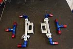 As you can see from the image to the right these look very swanky bits of kit. Prepped and sprayed, they look like original equipment, but as can be seen clearly in the image, each rail has two inlets. You will also notice the nice annodised unions. These are all aeroquip fittings which ensure a proper, reliable fitment to the fuel pipe (which is separate to this image). I have seen a number of fuel rail kits use push on fittings.... whilst these may be ok, you really need to invest in something that will seal properly and remain sealed.... the last thing you want is fuel spraying all over your hot engine! All the API parallel fuel rail kits will come with aeroquip fittings and braided fuel lines if requested.
API Engines have been modifying standard fuel rails for some years now and whilst you can go and buy brand new rails that already have an inlet at each end, customers using API's parallel rails seem to swear by them. Of course API seem to think they are ok as well!
With the new Lateral 800cc injectors slotted in to the new API parallel fuel rails, the inlet manifold set-up was complete. That was the fuel system modifications complete.
Some of you may ask why we never touched the standard fuel pump at this stage. Whilst some tuners may of uprated to a better system, PowerStation had found through a lot of testing, that the standard Spec C fuel pump (which is a very good piece of kit) would be able to cope at the level we were hoping for. If for what ever reason we experienced issues, then we would of course look at tackling this area. Since no problems were envisaged the fuel pump side was left alone at this stage.
Since we had uprated the fuel injectors we also decided to uprate the standard fuel rails.
Why?
Well, the standard fuel rails (one rail per two injectors, located on each side of the inlet manifold) feed the fuel injectors with petrol. These standard rails have an inlet based at one end only. In theory (whilst this is perfectly ok for standard set-ups) this could mean a pressure drop of fuel feeding the injector at the opposite end of the injector rail to the one that has the inlet. On high powered modified engines this can cause issues, especially when the fuel supply is being uprated and expected to cope with much higher levels of performance.
API Engines have been modifying standard fuel rails for some years now and whilst you can go and buy brand new rails that already have an inlet at each end, customers using API's parallel rails seem to swear by them. Of course API seem to think they are ok as well!
With the new Lateral 800cc injectors slotted in to the new API parallel fuel rails, the inlet manifold set-up was complete. That was the fuel system modifications complete.
Some of you may ask why we never touched the standard fuel pump at this stage. Whilst some tuners may of uprated to a better system, PowerStation had found through a lot of testing, that the standard Spec C fuel pump (which is a very good piece of kit) would be able to cope at the level we were hoping for. If for what ever reason we experienced issues, then we would of course look at tackling this area. Since no problems were envisaged the fuel pump side was left alone at this stage.
Last edited by ex-webby; 05 February 2008 at 10:50 PM.
17 January 2008, 09:04 PM
#17
Oil Sump
 The engine as a complete unit with anxillaries was nearly built back up now. Everything bar the clutch had now been assembled and this mass of metal now actually ressembled the lump that originally came out of the Spec C's engine bay. I for one was starting to get quite excited.
Ok, so we had modified the fuel system to cope with the new engine and target power. It was now time to look at the oil supply system.
One of the areas of development that PowerStation under went with the Type25 Race Car were self evident issues with the standard configuration, especially concerning a car that was to be used on track.... as in the Project car. As part of the engine build the engine had already been spec'd with an uprated high pressure Cosworth oil pump to ensure a consistent supply of oil from the pump. This is only part of the story, as you may imagine during high grip / gravity corners the pump can only pump if oil is around the oil pick-up in the sump. Going around a corner has the affect of sloshing the oil to one side of the sump, therefore not enabling the oil pick-up to suck up oil. If this happens then oil starvation will emerge which is not so good for items of the engine that need constant and consistant lubrication. Ultimately with the standard oil pick up arrangement, this can (under track conditions) lead to a damaged engine..... not what we wanted.
There are many ways you can prevent this and many areas that may need preventative measures in place to stop all kinds of oil starvation issues. Unfortunately there are also many available parts that do not actually work efficiently, so you really have to be careful with modifications around the oil system.
This was an area that PowerStation had a vast amount of real competition Subaru experience in off the back of (in part) the 2006 Time Attack season. Luckily we would be able to tap in to this priceless experience and adopt modifications and knowledge learnt in our Project car.
The first area to attack would be that of the sump.
 As explained earlier the oil pick-up (or lack of when driving quickly around a bend with a lot of lateral grip) needed to be sorted to ensure that oil was always around this area regardless of the environment the car would be in.
As you can see from the image to the right, the oil pick-up (in the middle of the image pointing up) is in the centre of the sump. You can probably appreciate that this location with a sump with no modifications (as it has nothing in it in reality) can let oil move from side to side and in cases miss the pick-up under certain conditions.
Ok, so we had modified the fuel system to cope with the new engine and target power. It was now time to look at the oil supply system.
One of the areas of development that PowerStation under went with the Type25 Race Car were self evident issues with the standard configuration, especially concerning a car that was to be used on track.... as in the Project car. As part of the engine build the engine had already been spec'd with an uprated high pressure Cosworth oil pump to ensure a consistent supply of oil from the pump. This is only part of the story, as you may imagine during high grip / gravity corners the pump can only pump if oil is around the oil pick-up in the sump. Going around a corner has the affect of sloshing the oil to one side of the sump, therefore not enabling the oil pick-up to suck up oil. If this happens then oil starvation will emerge which is not so good for items of the engine that need constant and consistant lubrication. Ultimately with the standard oil pick up arrangement, this can (under track conditions) lead to a damaged engine..... not what we wanted.
There are many ways you can prevent this and many areas that may need preventative measures in place to stop all kinds of oil starvation issues. Unfortunately there are also many available parts that do not actually work efficiently, so you really have to be careful with modifications around the oil system.
This was an area that PowerStation had a vast amount of real competition Subaru experience in off the back of (in part) the 2006 Time Attack season. Luckily we would be able to tap in to this priceless experience and adopt modifications and knowledge learnt in our Project car.
The first area to attack would be that of the sump.
As you can see from the image to the right, the oil pick-up (in the middle of the image pointing up) is in the centre of the sump. You can probably appreciate that this location with a sump with no modifications (as it has nothing in it in reality) can let oil move from side to side and in cases miss the pick-up under certain conditions.
Last edited by ex-webby; 05 February 2008 at 10:53 PM.
19 January 2008, 02:39 PM
#18
To stop this from happening requires the internals of the sump to be modified with gates (to stop the oil from moving from side to side quickly - it still needs the ability to do this, but in a more controlled and slower manner), along with anti-surge technics (like a tube) around the pick-up itself.
PowerStation has the facilities to frabricate a number of parts in-house and as with the Type25 Race Car, the insert for the sump was left to the in-house fabrication expert, Fuzz.
Using the same design of sump insert that was bluebprinted and proved within the Type25 Race Car, Fuzz created another masterpiece for this car.
Unfortunately (as with a number of specifics of these articles) we are unable to show you pictures of this sump conversion... it wouldnt be right to give away the development and design. Needless to say, if this sump design was good enough for the Type25 Race Car, it was certainly going to be good enough for us.
Other areas of the oil system would also be modified and these will be explained further on.
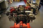
 With the engine work now complete, it was finally down to the job of taking the engine off the stand, sticking it on an engine hoist and putting the clutch on. At this stage, the engine was now ready to go back in to the cars' engine bay.
Cosworth Engine back in engine bay
 Well.... it had now come the time to place the new Cosworth engine in to the Spec C engine bay. As you may appreciate seeing this happen does get you (the customer) quite excited, especially as you may personally see the complete transformation first hand. Not many people are able to witness a job of this magnitude from end to end and whilst some are not interested, the amount you learn just by witnessing these processes is truly unbelievable.
The engine went back in as easy as it came out..... but of course we had one item that could cause an upset, that was the new turbo position with the modified up-pipe. Unfortunately it was found that very slight adjustment (this would have been a total nightmare if Nick hadn't of done an excellent job in the first instance after spending the time measuring) needed to be made to the up-pipe. This was soon made and everything bolted up as it should. The new Cosworth engine was now in the car, with the complete exhaust system in place..... everything as it should be!
It is probably worth mentioning at this point that due to the fact that the new AET turbo was of the single scroll variety, the previous ScoobySport exhuast downpipe was a twin scroll. As described in Stage 1, the fitment is totally different, so we decided to fit a complete new system. This time supplied by Miltek. Staying with a similar specification to the previous ScoobySport system we chose to install a 3" decat design. Again this was chosen off the back of testing that PowerStation had completed with both the Type25 Race and Road car, so we knew that the system was matched to the Cosworth engine set-up.
PowerStation has the facilities to frabricate a number of parts in-house and as with the Type25 Race Car, the insert for the sump was left to the in-house fabrication expert, Fuzz.
Using the same design of sump insert that was bluebprinted and proved within the Type25 Race Car, Fuzz created another masterpiece for this car.
Unfortunately (as with a number of specifics of these articles) we are unable to show you pictures of this sump conversion... it wouldnt be right to give away the development and design. Needless to say, if this sump design was good enough for the Type25 Race Car, it was certainly going to be good enough for us.
Other areas of the oil system would also be modified and these will be explained further on.
Cosworth Engine back in engine bay
The engine went back in as easy as it came out..... but of course we had one item that could cause an upset, that was the new turbo position with the modified up-pipe. Unfortunately it was found that very slight adjustment (this would have been a total nightmare if Nick hadn't of done an excellent job in the first instance after spending the time measuring) needed to be made to the up-pipe. This was soon made and everything bolted up as it should. The new Cosworth engine was now in the car, with the complete exhaust system in place..... everything as it should be!
It is probably worth mentioning at this point that due to the fact that the new AET turbo was of the single scroll variety, the previous ScoobySport exhuast downpipe was a twin scroll. As described in Stage 1, the fitment is totally different, so we decided to fit a complete new system. This time supplied by Miltek. Staying with a similar specification to the previous ScoobySport system we chose to install a 3" decat design. Again this was chosen off the back of testing that PowerStation had completed with both the Type25 Race and Road car, so we knew that the system was matched to the Cosworth engine set-up.
Last edited by ex-webby; 05 February 2008 at 10:55 PM.
19 January 2008, 05:01 PM
#19
Front Mounted Intercooler
Another change for this stage of modification was to be around the facilities to cool the charge air temps between the turbo and engine. As touched upon in previous articles, and up to this point, this had been efficiently dealt with by means of the standard STi8 top mount intercooler. Again due to both the intended use and power output of this car, it was decided that this specific area needed something more up to the job of keeping charge temps as low as possible.
It had to be a Front Mounted InterCooler (FMIC).
One of the downfalls of using this type of intercooler is inherent in the Subaru engine layout and is caused by excessive pipe runs between the FMIC and the engine inlet (and outlet in this case). If you think about it logically, it will would take longer to pressurise a system with more pipe work, which in essence can lead to decreased response.
One of the ways this can be reduced is by reducing the pipe work required (sounds obvious I know) and this in turn can be done by turning the inlet manifold 180degs, so the inlet is pointing towards you (as you look at the engine bay) and thus achieves a much shorter pipe run ro the FMIC. The outlet from the turbo is still the same, but overall you are saving a fair bit of required travel. This was the route that PowerStation decided to take with the Type25 Race Car.
Overall the benefits of the decrease in charge temps from a well designed FMIC can be very good. Whilst these benefits may not be felt on the road so much (but beyond a certain power level will be a prerequisite regardless) at certain levels, it is on track you would deem the most benefit.
Upon completing some research, I have to say that a number of the FMIC kits available do not look nice in the engine bay. I don't mean the intercooler itself, but all the pipe work. I have seen a number of kits where the pipe work looks very tatty and cheap. This was certainly not the kind of experience we wanted to have.
AET Turbos were one of the companies we spoke to, especially as they are Hyperflows' official distributor for the UK. We were more than impressed with what we heard and saw.
Last edited by ex-webby; 05 February 2008 at 10:56 PM.
19 January 2008, 06:16 PM
#20
Until you have seen the size and quality of the Hyperflow FMIC, I doubt you have experienced these two words in the same sentence before. The Hyperflow "MONSTER" FMIC is the worlds largest commercially available intercooling system for the Impreza, developed to support extreme power outputs.
The FMIC includes features such as optimised turbulator density to reduce flow, heat rejection increased by 50%, flow area increased by 45%, all pipework is CNC mandrel bent, includes a unique integral bar support design, designed to retain factory fog lights, comes with hand polished end tanks and pipework and is ready to bolt on without any modifications.
If this performs as good as it looks, we will certainly be on to a winner!
Since we had found a FMIC that promised to deliver our basic needs, we decided not to bother with rotating the inlet manifold at this stage.
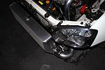 It is very difficult to show in pictures how H U G E this intercooler is, so thought it best to show you the unit fixed to the car. The unit (as promised) bolts straight on with the anxillaries supplied as part of the kit. Everyone who saw this core unit in the workshop all commented on its massive dimensions. How on earth it would fit on the car was a mystery at first, but again by using the supplied instructions it was a fairly painless excercise.
As is clearly seen by the picture to the right, the dimensions are on the large side. If you compare the core depth against many others available on the market you will see this is nearly twice as thick as most others. Whilst the core depth is not a gaurantee of efficiency, the design of this core (which you can not see) is extremely efficient. Couple this with the actual size and you can be rest assured this is one of, if not the best, FMIC currently available for the Impreza off the shelf.
As with nearly all FMIC, the front bumper needs modification to suit (this is perhaps the only fiddly job to complete when fitting a FMIC). Especially in this case because of the depth of the core, a fair chunk of bumper around the lower air duct (below the number plate) had to be cut away. Obviously this needs to be done as neatly as possible as the last thing you want is a job ruined by a "cat & shut" bumper modification. Needless to say PowerStation came to the rescue and did a stirling job in modifying the lower bumper section, to the degree that the whole install looked OE.
The FMIC includes features such as optimised turbulator density to reduce flow, heat rejection increased by 50%, flow area increased by 45%, all pipework is CNC mandrel bent, includes a unique integral bar support design, designed to retain factory fog lights, comes with hand polished end tanks and pipework and is ready to bolt on without any modifications.
If this performs as good as it looks, we will certainly be on to a winner!
Since we had found a FMIC that promised to deliver our basic needs, we decided not to bother with rotating the inlet manifold at this stage.
As is clearly seen by the picture to the right, the dimensions are on the large side. If you compare the core depth against many others available on the market you will see this is nearly twice as thick as most others. Whilst the core depth is not a gaurantee of efficiency, the design of this core (which you can not see) is extremely efficient. Couple this with the actual size and you can be rest assured this is one of, if not the best, FMIC currently available for the Impreza off the shelf.
As with nearly all FMIC, the front bumper needs modification to suit (this is perhaps the only fiddly job to complete when fitting a FMIC). Especially in this case because of the depth of the core, a fair chunk of bumper around the lower air duct (below the number plate) had to be cut away. Obviously this needs to be done as neatly as possible as the last thing you want is a job ruined by a "cat & shut" bumper modification. Needless to say PowerStation came to the rescue and did a stirling job in modifying the lower bumper section, to the degree that the whole install looked OE.
Last edited by ex-webby; 05 February 2008 at 10:58 PM.
19 January 2008, 07:58 PM
#21
Induction Kit
With the Hyperflow FMIC in place (and as a result of fitting most FMIC kits) we had to look at altering our method for induction. Again discussed in previous stages, we found the standard airbox with the addition of an uprated panel filter to be the most effective. Whilst we did test one induction kit, we found both issues with it's use and also with the cost. However, due to the fact that we now needed some form of aftermarket induction kit (since the airbox had to be removed due to the FMIC piping from the turbo) this was our next item to be researched.
Fortunately for us the research did not take too long.....
Part of a complete kit from Hyperflow, you can also purchase an induction kit (as Hyperflow recognise the issue with the FMIC pipework). This is no ordinary induction kit mind you, as it utilises the inner wing design which enables the induction kit to be sited within an area that is free from high engine temperatures (not good for induction kits) and ensures a nice cold air supply.
Without question the inner wing location was paramount for the induction kit and whilst many people sell and have fitted under bonnet induction kits, we would certainly not recommend it. It is possible to overcome the heat issue to a degree (when moving, but not when stationary), but this requires additional cold air ducting. The issues we had experienced in previous stages with surge would also not be an issue in this stage, since we had a bigger engine (that could consume more air) and a totally different turbo set-up.
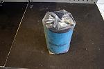 This type of induction had already been proven and used on the Type25 Race Car (you starting to get the feeling that the Type25 Race Car and the Project car are becoming more and more linked in their designs?!), so it was a no brainer that this should be the type of induction kit to use.
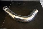 Because of the location within the inner wing, the induction kit comes with another high quality aluminium tube (to the same quality standards as the Hyperflow FMIC piping) to connect to the MAF / turbo inlet pipe. This of course helps with the standardisation of the look under the bonnet. The filter itself is made of a sponge type material, which is different to a number of kits which are made of a paper meshed type design. As the car was going to stay with the existing MAF based airflow mapping, we had to ensure that this filter was MAF friendly. We needn't of worried, as that is exactly what it is.... MAF friendly, as it does not have gallons of filter oil (to aid filtration, but too much is a MAF killer) soaked in it.
So, with the Hyperflow inner wing induction kit now fitted we were now in a position to move on to the next area of modification.
With the Hyperflow FMIC in place (and as a result of fitting most FMIC kits) we had to look at altering our method for induction. Again discussed in previous stages, we found the standard airbox with the addition of an uprated panel filter to be the most effective. Whilst we did test one induction kit, we found both issues with it's use and also with the cost. However, due to the fact that we now needed some form of aftermarket induction kit (since the airbox had to be removed due to the FMIC piping from the turbo) this was our next item to be researched.
Fortunately for us the research did not take too long.....
Part of a complete kit from Hyperflow, you can also purchase an induction kit (as Hyperflow recognise the issue with the FMIC pipework). This is no ordinary induction kit mind you, as it utilises the inner wing design which enables the induction kit to be sited within an area that is free from high engine temperatures (not good for induction kits) and ensures a nice cold air supply.
Without question the inner wing location was paramount for the induction kit and whilst many people sell and have fitted under bonnet induction kits, we would certainly not recommend it. It is possible to overcome the heat issue to a degree (when moving, but not when stationary), but this requires additional cold air ducting. The issues we had experienced in previous stages with surge would also not be an issue in this stage, since we had a bigger engine (that could consume more air) and a totally different turbo set-up.
So, with the Hyperflow inner wing induction kit now fitted we were now in a position to move on to the next area of modification.
Last edited by ex-webby; 12 February 2008 at 10:48 AM.
21 January 2008, 05:08 PM
#22
Dump Valve
Part of the Hyperflow FMIC kit allows smart location of a dump valve (unlike some cheaper kits), containing all the bracketry and pipe work required. Whilst we could of made do with the standard dump valve, we decided to uprate this item to match the rest of the system being adopted.
A dump valve plays an important part within the overall air intake / turbo system as it allows excess air pressure to be vented off from within the system when the turbo comes off throttle / boost (between the compressor and inlet manifold). If no dump valve was present this excess air pressure would want to push itself back through the turbo compressor, which would cause the compressor to stall. Whilst the stalling is not an immediate problem (but can cause response issues when trying to come back on throttle / boost), this sharp oscillation can cause issues with the compressor wheel itself, sometimes resulting in failure.
A number of people choose to remove dump valves on turbo installs, as they say it increases response (presumably along the lines of it being better to keep the system as pressurised as possible). One way you can look at it, if it was not actually doing (of benefit) anything then why would car manufacturers fit them to begin with.
A number of people also like the noisy ones! This is based on a dump valve that instead of venting the excess air back through the intake system, they vent to atmosphere. This set-up enables the traditional dump valve noise to be heard.
Since we didnt want a noise maker, we decided on an uprated dump valve that would not vent to atmosphere.
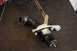 For the supply of the required dump valve we again turned to AET Turbos, who supply and distribute the Turbosmart range of (amongst other performance items) performance dump valves.
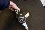 For our application AET Turbos recommended the Turbosmart Subaru dual port dump valve as the weapon of choice. This dump valve is three types of dump valve in one. Not only does it enable you to configure it's set-up to vent to atmosphere, but you can also vent back into the air intake or both! As well as being multi-purpose, you also have the ability to change the strength of the spring against the piston. If you say wanted more noise (for a vent to atmosphere set-up) or had running issues (you can experience rough idling and/or poor running) you are able to apply more pressure to the spring so to make more or less noise or enable the valve to dump faster or slower (depending on set-up and requirements). Ultimately it makes this dump valve one of which is fully adjustable.
With the Turbosmart dump valve being very easy to fit and set-up, we were again ready to move on to yet another area of modification.
Part of the Hyperflow FMIC kit allows smart location of a dump valve (unlike some cheaper kits), containing all the bracketry and pipe work required. Whilst we could of made do with the standard dump valve, we decided to uprate this item to match the rest of the system being adopted.
A dump valve plays an important part within the overall air intake / turbo system as it allows excess air pressure to be vented off from within the system when the turbo comes off throttle / boost (between the compressor and inlet manifold). If no dump valve was present this excess air pressure would want to push itself back through the turbo compressor, which would cause the compressor to stall. Whilst the stalling is not an immediate problem (but can cause response issues when trying to come back on throttle / boost), this sharp oscillation can cause issues with the compressor wheel itself, sometimes resulting in failure.
A number of people choose to remove dump valves on turbo installs, as they say it increases response (presumably along the lines of it being better to keep the system as pressurised as possible). One way you can look at it, if it was not actually doing (of benefit) anything then why would car manufacturers fit them to begin with.
A number of people also like the noisy ones! This is based on a dump valve that instead of venting the excess air back through the intake system, they vent to atmosphere. This set-up enables the traditional dump valve noise to be heard.
Since we didnt want a noise maker, we decided on an uprated dump valve that would not vent to atmosphere.
With the Turbosmart dump valve being very easy to fit and set-up, we were again ready to move on to yet another area of modification.
Last edited by ex-webby; 12 February 2008 at 10:47 AM.
21 January 2008, 06:35 PM
#23
Oil Breather / Separator System
As mentioned earlier on in this article, and whilst we had already started to modify part of the oil delivery system, we had further work to complete on the oil system for the new Cosworth engine.
Ok, so we had modified the sump to alleviate any possible surge issues within that initial area, but what about the increased pressures that would now be apparant within a system producing a lot more bhp under more extreme circustances?
Again, one specific area (with the whole engine and anxillary set-up) was that of increased durability and reliability.
As PowerStation had gained a lot of experience with regards to oil surge issues, they had also gained a lot of experience and knowledge regarding other areas of the oil system, which in this specific case was around how to make the system breathe better.
So what does all this mean?
Sufficient "crankcase breathing" is a very important function of any engine. Even in new engines, the pressures created by the combustion process will cause gas to pass the pistons rings into the crankcase. If a given engine's breather system is not up to the job (or becomes blocked / restricted) a whole magnitude of issues can materialise. These issues can range from blown oil seals, oil ring failure on pistons (increasing contamination of petrol and oil - not good for your engine internals) and detonation etc.
For moderate levels of tune the standard breather system is normally more than adequate, but with a set-up that has a major increase in power or used for motorsport functions (higher, sustained revs), it is imperative that sufficient engine ventilation is allowed for.
With higher combustion pressures, higher oil pressures and higher engine speeds, the demand for adequate crankcase ventilation will also be higher.
Under PowerStations instruction / specification (based on their Type25 Race Car) we sought advice on parts for the Project cars breather system, and again we called upon AET Turbos to supply the required parts.
Not just satisfied with producing high quality FMIC and induction kits, Hyperflow also produce complete oil breather systems. Based on the quality of the other products we had already installed, as long as the breather system matched the specification that PowerStation insisted on, it made perfect sense to use Hyperflows hardware. To enable efficient breathing of the engine, PowerStation requested a system that contained a catch tank with two inlets and one outlet. This would enable two areas of the engine to act as the breathing outlets, whilst the third tap on the can (the outlet) would enable this pressure to be vented off.
Last edited by ex-webby; 05 February 2008 at 11:01 PM.
21 January 2008, 07:38 PM
#24
PowerStation had already added an additional tap (inlet) to the sump as part of a previous modification, and should it be required (although PowerStation knew how efficient the Cosworth engine was at breathing, so should not of needed it at this level) we would be able to utilise a catch tank in the future that would enable us to drain any excess oil in the catch tank back to the sump. Based on current requirements we decided that a catch tank with a drain plug would not be required at this stage.
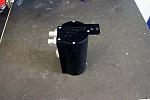 As expected, the Hyperflow oil catch tank was of an extremely high quality. Annodised in black (to match the rest of the engine bay and to look as OE as possible), the supplied catch tank had three taps. For our purposes (as previously stated) we would use two for inlets from the engine and one as the vent to complete the breather system.
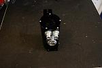 The idea of this breather system is to first vent excess pressure from the engines combustion system in to the tank. This then acts as a separator, which enables the heavy substance from the engine vapour (in this case oil) to drop to the bottom of the tank, whilst the gas element is vented out to atmosphere. This catch tank also has the added benefit of a glass window, which enables you to see the level of any oil that has dropped (contained in the vapour). Should this prove to be substantial (which was not envisaged), you could either empty the catch tank of this oil, or better, modify the tank (or find one that can) to return this oil back to the sump.
As with other previous specifics, we are unfortunately unable to discuss the specific "plumbing method" used for this system, but suffice to say it was very neat and above all else should prove to be very functional and efficient.
Well.... that was about it. Job done and time to go home then?!? Not quite.
Running the completed engine up
With the Cosworth engine, new uprated and standard anxillaries now place within the engine bay it was time to start the new engine checking and running in process.
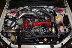 Upon completion of the the install, not only had we completed what we set out to do (construct an engine capable for our power goals, with the intention of having parts that would hopefully ensure reliability as well - but only time would tell on this front), but we also had (even though I must say so myself) one sweet looking engine bay. Ok, it was not THE most important factor of the conversion, but certainly something that we wanted to maintain. Too many times have I seen conversions that make the engine bay look "half cocked" and cheap... albeit I am sure these conversions are functional, there are certainly parts available that maybe you have to pay a bit more money for, but by christ do they make the end job look that much better, without going too bling!
As with other previous specifics, we are unfortunately unable to discuss the specific "plumbing method" used for this system, but suffice to say it was very neat and above all else should prove to be very functional and efficient.
Well.... that was about it. Job done and time to go home then?!? Not quite.
Running the completed engine up
With the Cosworth engine, new uprated and standard anxillaries now place within the engine bay it was time to start the new engine checking and running in process.
Last edited by ex-webby; 05 February 2008 at 11:02 PM.
21 January 2008, 08:39 PM
#25
With PowerStation completing the fitment of this new set-up it was time to give the engine it's initial run on their dyno (no, no, no.... I don't mean any full hammer poweruns here). This was done via a tweaked Type25 Road Car map to suit our specification for this early stage in the running in process (again another advantage of having PowerStation involved!).
After the engine had been hand primed (to ensure oil pressure was up to desired levels) the ignition was engaged and low and behold the car fired up after a couple of turns, and what a sweet sounding engine it was!!
With the Project car once again strapped down on PowerStations rolling road, PowerStation did a number of alterations to the Type25 Road Car map using the ECUTEK software to produce our own running in map. Limiting parameters like boost and ignition, whilst ensuring that fueling was correct, the car was gently ran up on the rollers in various gears and revs as part of the initial stage of checking all is well. One of the major benefits of doing this on a rolling road is that you can check in situ the engine and anxillaries for leaks etc.
Over the next few days the car was ran from cold (to ensure cold start was fine) and a few more miles where put on the engine until PowerStation were happy that it was fit to be released for us to complete the running in process.
Why run the engine in and what does this process consist of?
As with a number of items that are cast or machined you must bed internal parts in. I suppose you could relate this to a male and female connection that needs to be mated together. To ensure that parts are bed in, you should complete a running in period. This is when the engine is ran under normal road conditions, but up to lower than normal speeds using various levels of load / gearing. This will ensure that both the mating and heat up / cool down processes are completed under a prescribed environment. It is important that whilst not too much stress is put on a fresh engine immediately, minimal stress is also to be avoided.... you need to find a happy medium. This is normally prescribed as keeping revs below a certain level, but varying revs and load (i.e. use the gearbox more). Keeping the engine at constant revs (i.e. say on the motorway etc), even below the prescribed rev limit, can cause problems with the running in process (relating to things like glazing). Some engines require very little running in and because of exacting tolerances and parts used the Cosworth engine was one of these types, but in the vein of normality we completed the running in process, even though it was a lot shorter than what you would normally expect for say a standard engine.
Last edited by ex-webby; 05 February 2008 at 11:03 PM.
21 January 2008, 10:04 PM
#26
TEST 1 Base Figure � Overview
With the running in period completed (and the engine / car completely checked over) within a matter of days, it was time to return to PowerStation to start the initial mapping sessions. You may wonder why we have not discussed how the car felt during the run in period. Whilst this may of been informative, with the constraints in place, it would certainly of not given a full picture to how this engine surely would respond when unleashed..... this information we thought, should be discussed in detail further on after the potential was sought after a good few mapping sessions.
As with Stage 1 & 2, at this point we decided to stick with the trusty OE ECU and use the preferred mapping software that is ECUTEK. For those that do not know, the Type25 Race Car used MOTEC for its brain, which had proved its worth over the previous 12 months with the race cars outings and achievements. Since we did have a budget (even though it was far from small) and we wanted to see what was possible from specific OE items, it was decided to stick with the standard ecu and ECUTEK to see how far these items could be pushed. Not only would we be sticking with the standard ECU under the control of ECUTEK, but as previously, the remit was to stick with normal pump fuel (in this case VPower). In too many cases are people running a mix of pump fuel and octane booster or straight race fuel to achieve big hp figures. Whilst this is fine and dandy, again we wanted to see what was possible with keeping specifics "normal".
Using the Type25 Road Car's map as the base, PowerStation started the long process of remapping the ECU. As discussed during previous stages, various elements to do with boost, fuel and ignition were reprofiled to take in to account the new engine and anxillary set-up.
Being ever more inpatient, it was torturous to stand-by watching run after run taking place as Rich & Fuzz made changes via the laptop, without me knowing specifically (by way of a RR graph) what was being achieved.
I was told it all needs to be done one step at a time and as a general overview it would be fueling and boost sorted first and then finally ignition. All I can say at this point is this engine sounded fantastic during it's acceleration runs on the dyno. With a different set-up to both the Type25 road and race car, each stage had to be checked and double checked to ensure the results were ok and the response from the engine was as expected.
It had finally come the time for some proper power runs. This first one would be classed as the Base Line for future runs within this article.
Last edited by ex-webby; 05 February 2008 at 11:04 PM.
22 January 2008, 05:29 PM
#27
TEST 1 - Base Line - Summary of Spec
Cosworth 2.5 engine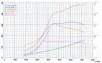
AET Turbo
Lateral 800cc Injectors
Hyperflow Induction Kit
Hyperflow FMIC
SFS inlet hose
Miltek 3" Decat Exhaust System
ECUTEK remapped ECU
Peak Boost - 1.60bar
Fuel - VPower
The Base Line figure achieved was 481.2bhp @ Flywheel with 622.2Nm (458.85 lb ft) torque
TEST 1 - Base Line - Comments
WOW.... with the first real set of power runs under our belt the new set-up reached a brilliant start as regards to power figures. Although I was slightly annoyed with the fact that we hadn't reached the magic 500bhp (what was I thinking to expect this, this early on in the build), what the above graph does not show you is the response early on in the rev range against previous stages of modification.
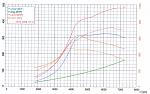 Just taking the power graph in isolation the image to the right shows the comparison (overlay) between the current engine set-up and tune, compared to a latter test in Stage 1 (unfortunately we never managed to keep any dyno print outs from Stage 2, due to a hardware issue). At this point in time in Stage 1, the car achieved circa 360bhp / 355lb ft. These figures are irrelevant to a point, as that is not the most interesting point of comparison.
So lets discuss this second overlay graph.
If you remember back to Stage 1, the lowdown pull was a paramount part of the original Twin Scroll set-up. Having a set-up that combined excellent low down torque / power made for an ultra quick road car.... easily the main benefit of a twin scroll system.
Having a look at the overlay graph, whilst it is easy to see which lines are from which test from about 3500rpm onwards (just incase you wondered, the higher plots are from the new set-up!), from just below 2000rpm to about 3500rpm is the interesting bit!!
Although it is hard to differentiate, the lines that are the highest of the four (until it gets to the point that they all become inter-mingled) are from this latest set-up. Based on that fact you can see clearly that with the new set-up achieves higher bhp and torque figures for the same RPM as the modified 2ltr twin scroll set-up.
Now lets think about this some more.....
Cosworth 2.5 engine
AET Turbo
Lateral 800cc Injectors
Hyperflow Induction Kit
Hyperflow FMIC
SFS inlet hose
Miltek 3" Decat Exhaust System
ECUTEK remapped ECU
Peak Boost - 1.60bar
Fuel - VPower
The Base Line figure achieved was 481.2bhp @ Flywheel with 622.2Nm (458.85 lb ft) torque
TEST 1 - Base Line - Comments
WOW.... with the first real set of power runs under our belt the new set-up reached a brilliant start as regards to power figures. Although I was slightly annoyed with the fact that we hadn't reached the magic 500bhp (what was I thinking to expect this, this early on in the build), what the above graph does not show you is the response early on in the rev range against previous stages of modification.
So lets discuss this second overlay graph.
If you remember back to Stage 1, the lowdown pull was a paramount part of the original Twin Scroll set-up. Having a set-up that combined excellent low down torque / power made for an ultra quick road car.... easily the main benefit of a twin scroll system.
Having a look at the overlay graph, whilst it is easy to see which lines are from which test from about 3500rpm onwards (just incase you wondered, the higher plots are from the new set-up!), from just below 2000rpm to about 3500rpm is the interesting bit!!
Although it is hard to differentiate, the lines that are the highest of the four (until it gets to the point that they all become inter-mingled) are from this latest set-up. Based on that fact you can see clearly that with the new set-up achieves higher bhp and torque figures for the same RPM as the modified 2ltr twin scroll set-up.
Now lets think about this some more.....
Last edited by ex-webby; 22 January 2008 at 08:40 PM.
22 January 2008, 09:16 PM
#28
As previously found and accepted by many, the response of the 2ltr twin scroll set-up is impressive by anyones standards. The fact that not only does this new set-up achieve better results mid range and top end (that was to be expected), but this new set-up is also better lowdown when compared against the 2ltr twin scroll.
Breaking this down makes the results stand out even more......
FMIC - With all that extra pipe work and capacity it has been said in the past to decrease low end power / torque. Not this specific set-up!
Single Scroll Turbo - Ok... we are not talking apples and apples comparing a 2ltr to a 2.5ltr, but needless to say this turbo not only helps to produce better lowdown figures, but also produces the figures mid range and top end. This specific single scroll turbo certainly works!
2.5ltr Engine - I thought these are not supposed to rev very well or make power higher up the rev range when compared to a 2ltr. Mmmm... this engine does! This specific power run was only taken to 7275rpm and it is still making power!
Even looking at the boost profile (which apart from the slight spike at the start) is held very well and achieves these peak power figures at circa 1.5bar and 1.4bar respectively.
Also remember this engine was still "fresh" and had only covered around 400miles. These are not supposed to loosen up (and in affect release more power) until they have done a fair few 1k miles.
All in all we were very pleased with these INITIAL results, but a power graph is one thing.... lets see how this car performs on the road!
TEST 1 - Base Line - Road Test
After the initial mapping session I was ordered to take the car out on the road and see how it drove (together with logging facilities using Delta Dash)... I didn't need much persuasion!!
One of the first things you notice (or don't notice in this case) is how smooth and quiet the engine is on tick over. You immediately assume because something is highly modified it should be corse and lumpy... certainly not the case here.
The engine pulled (just as the RR graph had indicated) very easily and smooth from very little revs. The difference from the previous Stage 2 mods was very hard to distinguish between, as we new the differences up to the start of the mid-range would be negliable..... but this was not a bad thing and the new set-up was certainly no worse.
I have to admit I was slightly apprehensive about the use of a FMIC, especially regarding stories of woe concerning the response when compared to the original TMIC.
Last edited by ex-webby; 01 February 2008 at 11:28 AM.
22 January 2008, 10:20 PM
#29
Whilst it was obviously difficult to compare like for like based on the previously used TMIC (this is a totally different engine set-up now), I have to say that the response was much better than I originally thought it would be.
So.... how does it actually "go" on the road then!?!
Even though I had been slightly dissappointed with not breaking the 500bhp barrier, I need'nt have worried. This car on acceleration was leagues above the old set-up. It is so hard to describe how this new engine pulls.... the torque is phenominal.
It felt as good lowdown as the previous set-up, but the mid and high end was ballistic now. This is to the point that driving this car hard on the road, meant that real concentration was required. You really have to drive a car at this sort of power to appreciate the leap in performance it provides.
It has the kind of mid and high range pull that makes you (well it did me) need to back off the loud pedal. The types of speed that can be acheived with very little effort (and this was one of the major differences) is outstanding.
The previous 2ltr set-up required the car to be worked hard...... this set-up just pulls from nothing and begs for more of the same without the need to break in to a sweat!
This car had now been totally transformed!
During the initial logging session on the road a number of areas needed tweaking as regards to the map. We knew that a number of sessions on road would be required to enable these areas to be sorted.
Unfortunately due to the fact that ScoobyLive 2007 was only around the corner, our development prior to this event had been cut short. Even though, ScoobyLive would provide another environment to get some valuable feedback for the cars continued development..... oh, and we had some other modifications we wanted to try!
We had also been invited to show the car as a demo TOTB entry for JapFest 2007. This event was to be held a week before ScoobyLive, but would give us invaluable feedback on-track....... and give me some much needed time behind the wheel!!
All in all the initial testing stage certainly proved to be beneficial. We knew the process of getting everything right would take time and required plenty of testing and feedback. The next part of the journey began.
Last edited by ex-webby; 05 February 2008 at 11:05 PM.
28 January 2008, 11:32 AM
#30
On-Track - JapFest 2007
With the car checked over and a few (as time allowed) changes made, we set off for Castle Combe.
It was planned for the car (along with a select few TOTB cars) to run on-track during a demo session. It had also been announced that JapFest had ran a competition and the lucky winners (with our consent) would be able to passenger with us during an additional session.
With further, valuable time on-track who was I to turn this offer down!
I have to be totally frank with you here and say that I am not the quickest person round a race circuit. But as was proved in 2006 (i.e. TunerGP), the more practice you get behind the wheel, the better you will become. Not having driven the car on-track in over 6 months and having very little time in the car full-stop, I was a little more than slightly apprehensive about these initial track sessions.
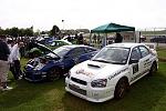 With the likes of Simon Norris and Adrian Smith in their respective monsters running in this demo session, I was even more nervous! Still, the car in it's new set-up and sporting it's 2007 graphic decals (thanks to Standard Signs) was ready to rock!
Having the ability to run any car on track (let alone something that has totally changed in it's drive like our car) is without doubt the best way to find out how your car handles and how you handle the car.
 Apart from the fact that I was fairly sedate (due to me... not the car), the engine felt very strong and because of the torque available from the engine / turbo set-up I found that I did not need to rev as high and could just ride the torque band.
The most important thing was that everything worked well and no issues were encountered..... as per usual, this car drove to and from the event on it's own steam.
The time on track (although short and sweet) proved that I needed much more time in the car to get the best from it, thus increasing my much needed confidence levels.
Again, after various data logs we could take what we learnt and carry on with set-up changes back at PowerStation. Unfortunately with ScoobyLive the following week, time was tight so the car was more or less checked over and prepared for the following weekends main event..... ScoobyLive.
With the car checked over and a few (as time allowed) changes made, we set off for Castle Combe.
It was planned for the car (along with a select few TOTB cars) to run on-track during a demo session. It had also been announced that JapFest had ran a competition and the lucky winners (with our consent) would be able to passenger with us during an additional session.
With further, valuable time on-track who was I to turn this offer down!
I have to be totally frank with you here and say that I am not the quickest person round a race circuit. But as was proved in 2006 (i.e. TunerGP), the more practice you get behind the wheel, the better you will become. Not having driven the car on-track in over 6 months and having very little time in the car full-stop, I was a little more than slightly apprehensive about these initial track sessions.
Having the ability to run any car on track (let alone something that has totally changed in it's drive like our car) is without doubt the best way to find out how your car handles and how you handle the car.
The most important thing was that everything worked well and no issues were encountered..... as per usual, this car drove to and from the event on it's own steam.
The time on track (although short and sweet) proved that I needed much more time in the car to get the best from it, thus increasing my much needed confidence levels.
Again, after various data logs we could take what we learnt and carry on with set-up changes back at PowerStation. Unfortunately with ScoobyLive the following week, time was tight so the car was more or less checked over and prepared for the following weekends main event..... ScoobyLive.
Last edited by ex-webby; 05 February 2008 at 11:07 PM.