Ive been askede a few times recently about the how to of this conversion. Found this excellent guide for y'all
THE WHAT:
This is an example how to convert an old EJ20G to work with '02+ WRX ignition coils.
THE WHY:
The EJ20G coils are notorious for failing with age and causing misfires. I had misfires at anything over 0.8 bar, that was traced to two coils that developed cracks in the housing. Below is what I found (I removed the cracked piece on the one on the right to see what was on the inside).
THE HOW:
The old style ignition incorporates an external igniter, the newer style has the igniter built into the coil housing. The old coils have 2 wires; coil trigger and +12V. The new coils have 3 wires; ground, igniter trigger, and +12v. There is a little bit of harness hacking to make it work, but it's pretty straight forward. Here are the basic steps;
1. Cut connector off of old coils
2. Wire the old pigtails to the new coils; Power to power, trigger to trigger. Wire the ground signal to a ring connector and attach to the mount screw
3. Install new coils and connect up to the Ej20G harness as usual
4. Remove the igniter, and snip the 2 connectors from the harness and merge the harness.
Details of the steps above:
1. This is pretty straight forward, just clip off as much of the pigtail from the old coils as possible.
2. The easiest solution is if you have the matching connectors for the new coils from the '02+ harness. I didn't, so I soldered new wires directly to the coils, then attached the old pigtails to the new wires.
Using the above picture as a reference, the pinning is as follows from left to right:
Pin1 : Pin2: Pin3
+12v : GND : Trigger
Red : Blk : Green <--- wire colors I used in my picture
RY : BY : GY <--- '02 WRX harness colors
After soldering the wires, I globbed in a bunch of high temp epoxy to prevent corrosion and to add some strain relief for the pins:
Next comes connecting the old connector to the new coil. You have two colors on the old pigtail, Red and Yellow (one of them might have a stripe, can't remember). Here's the tricky part of this, the wiring diagrams only show the wiring *up to* the coil connectors. The problem is in the diagram, the yellow wire is the +12V, but after the connector, on the coil side, the yellow wire turns into the trigger signal.
** To wire the pigtail to the new coils, connect the Yellow wire to the trigger pin on the new coil and the Red wire to the +12v pin. Put a ring terminal on the center pin wire.
Lastly I shrink tubed and put the ring terminal on the bolt (after cleaning the corrosion under the bolt flange)
3. The
coil fits in the early WRX heads perfectly, however there are some fitment issues with the Liberty version of the
motors. The engine harness has two
coil connectors for each side. The grey connector is for the front
coil, the black is for the rear.
4. Last part is to bypass the igniter. I chose to simply cut the connectors out of the harness and merge the harness. The igniter is on the backside of the mounting bracket containing the MAP sensor and boost control solenoid.
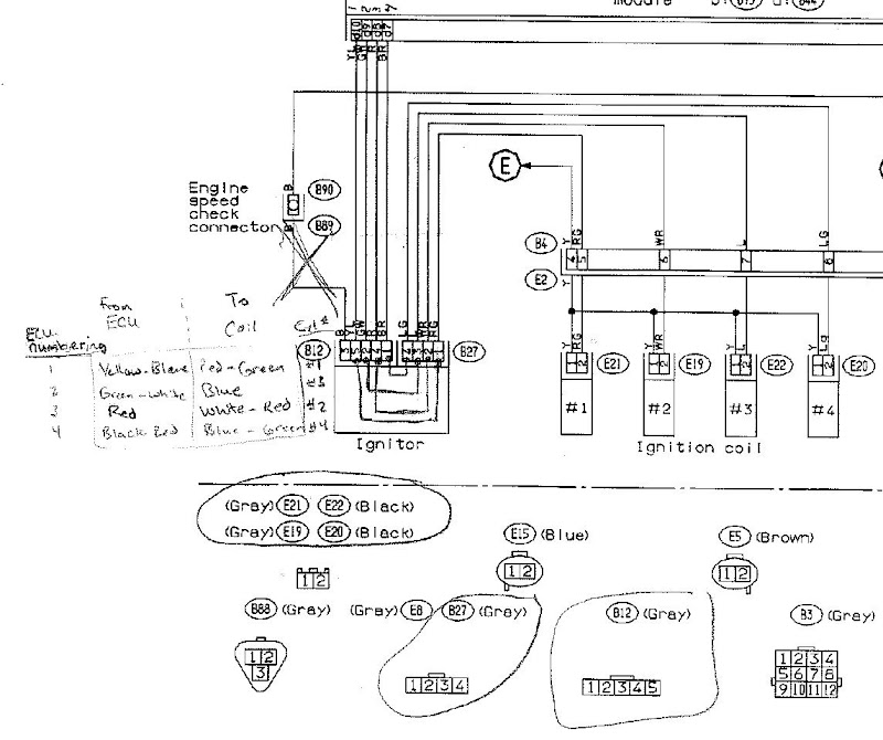
Cut both connectors out of the harness and remove the igniter. There are 5 input wires into the igniter from the main harness and 4 output wires leaving the igniter to the engine harness. If you are following from the wiring diagrams, this is a very confusing wire up. The signal pins on the ECU are labeled coil 1, 2, 3, 4. The wiring to the coils are also listed as Coil 1, 2, 3, 4. The trick is that they use different conventions. For the ECU, the pins are labeled in *firing order*. For the coils in the diagram, they are listed as the actual cylinder number. The correct wiring is:
ECU side :: Coil side
---------------------
Yellow-Blue stripe (YL) ---> Red-Green stripe (RG)
Green-White stripe (GW) ---> Blue (L)
Red (R) ---> White-Red stripe (WR)
Black-Red stripe (BR) ---> Blue-Green stripe (LG)
Black (B) ---> no connect
Wiring diagram for reference: